LDD-06 · Living Wing HVAC Distribution
One-line intent
Keep the trunk pure, the branches clean, and the air invisible.Design intent · AI render
FPO · AI render
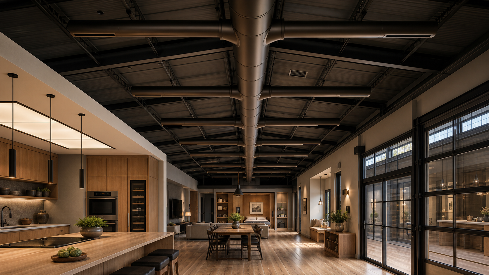
Living-wing ceiling intent render — interior looking north up the wing, the N-S main trunk and five E-W branches reading as architectural composition, not residential utility. For Position Only: AI-generated from the prompt below. Click to enlarge.
Locked decisions
- Main trunk: ~14" round, pre-insulated, N–S, ~12' from spine wall, sized for full build-out
- 5 E–W branches off the trunk, perpendicular only
- Local south service branch from mech room serving foyer / WC / stair base
- Branch takeoffs: smooth wye or angled, never hard 90°
- Diffusers: linear slot, 8–10 outlets, no diffuser over seating/table/cooking/entry/stair
Branch zones
| # | Zone |
|---|---|
| 1 | Entry · stair · mech (may be supplemented by local branch) |
| 2 | Kitchen work zone |
| 3 | Kitchen + breakfast (priority) |
| 4 | Living / TV |
| 5 | North / Murphy / bath |
Open items / engineer review
- Final trunk diameter (Manual D)
- CFM per branch + diffuser count
- Return air sizing + grille placement
- Make-up air interlock with kitchen island exhaust
Cost drivers
Linear slot diffusers $400–700/lf (premium vs round registers). ~30–50 lf = $12–35K. Smooth wye takeoffs $2–5K premium. Net: $15–40K above generic ducted install.Air-gap concerns
- Linear slot diffusers expensive to balance. Budget commissioning visit with smoke pen + anemometer.
- Trunk vs lighting centerline conflict — both want the living wing centerline. Coordinate.
- 5 branches × 12' apart may be over-engineered for residential CFM. Verify.
- Foyer "subtle local branch" risks being inadequate. Specify diffuser type + CFM target.
- Cooktop east-running duct may intersect main trunk + lighting. Coordinate before fabrication.
Cross-references
Diagram

Living-wing HVAC distribution plan — N–S 14" main trunk centered in the wing, 5 perpendicular E–W primary branches feeding linear slot diffusers, local south service branch off the mech room. Layer-2 CAD from
cad/source/06-living-hvac.py. Click to enlarge.Source Evidence
The living-wing sketches carry floor-plan intent that the HVAC plan only partly captures. Keep these visible until the second-floor program has its own controlled LDD or drawing.
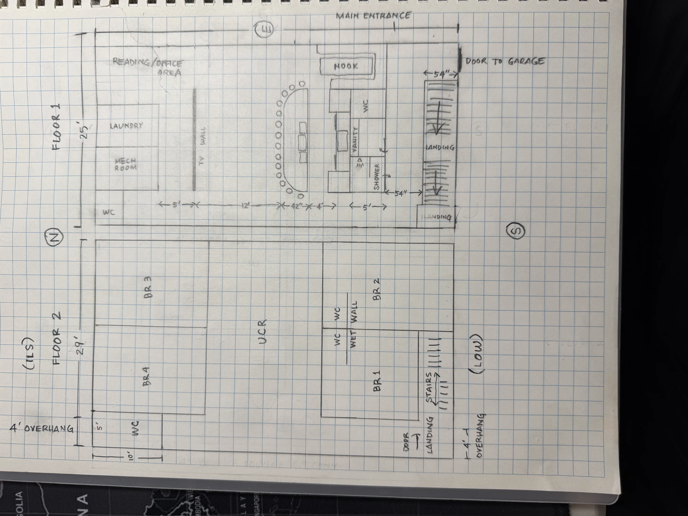
Living wing — both floors
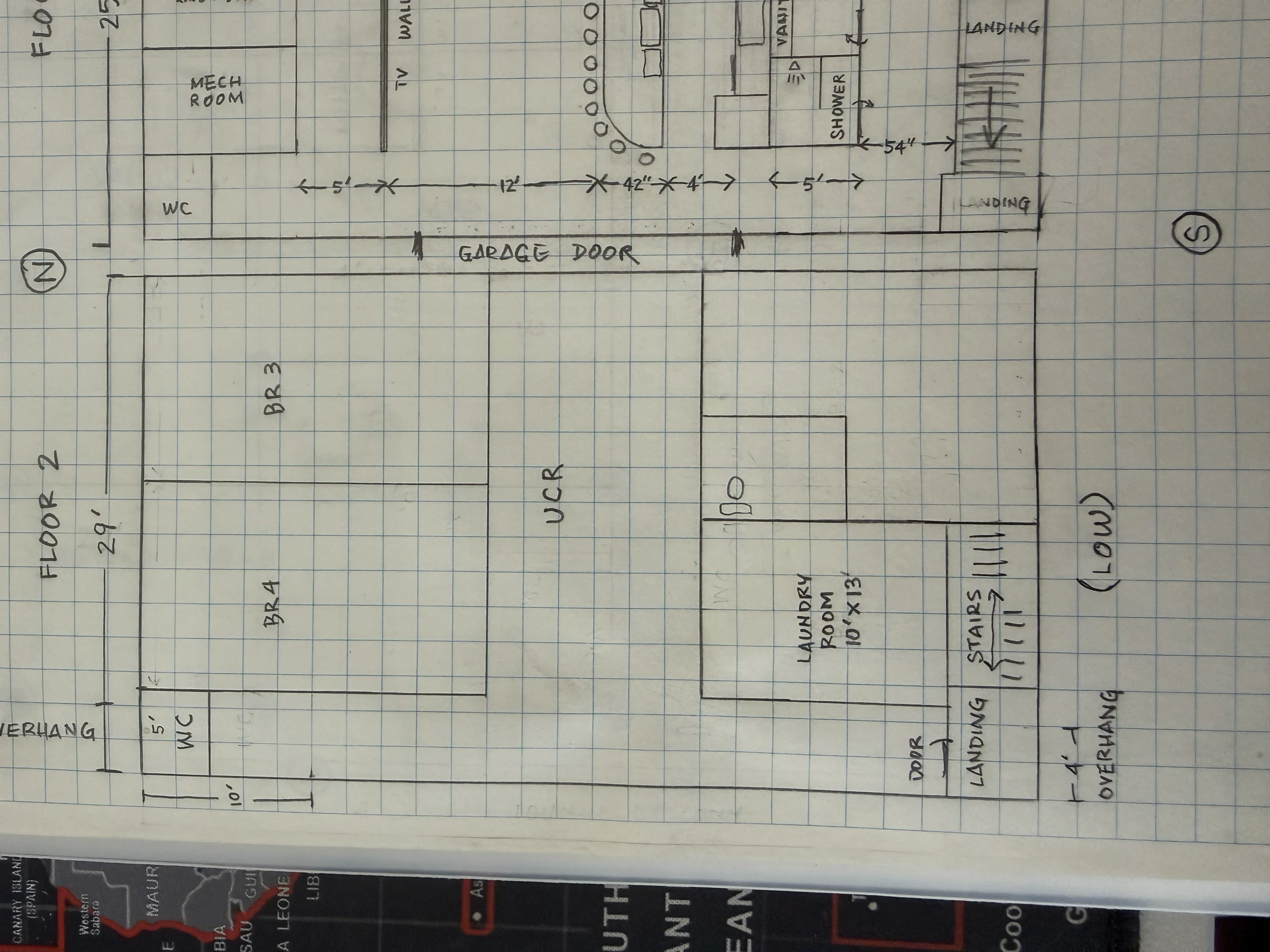
Floor 2 — bigger BR3 / BR4 variant
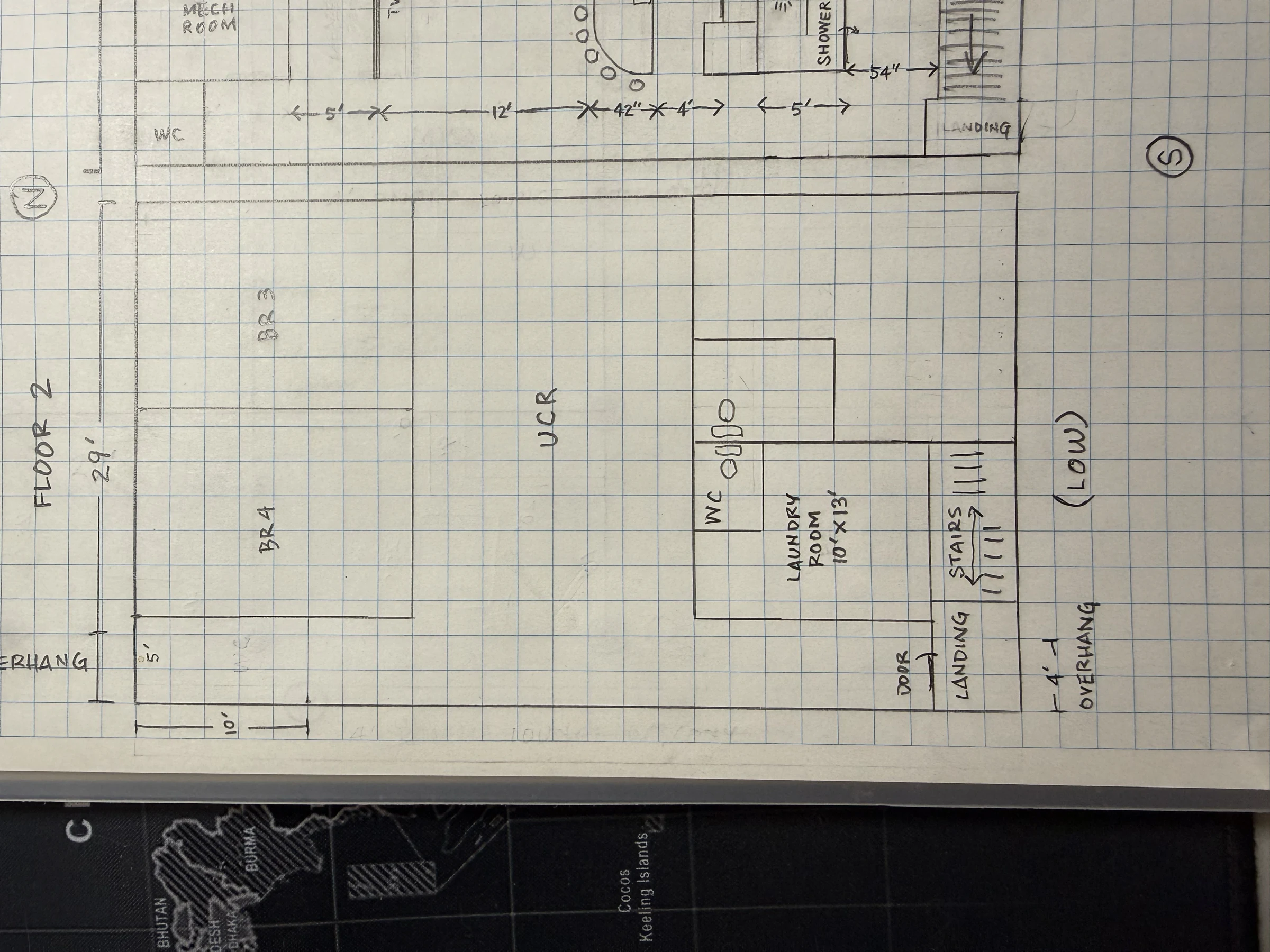
Floor 2 — WC in laundry-room variant