Plans + Sketches
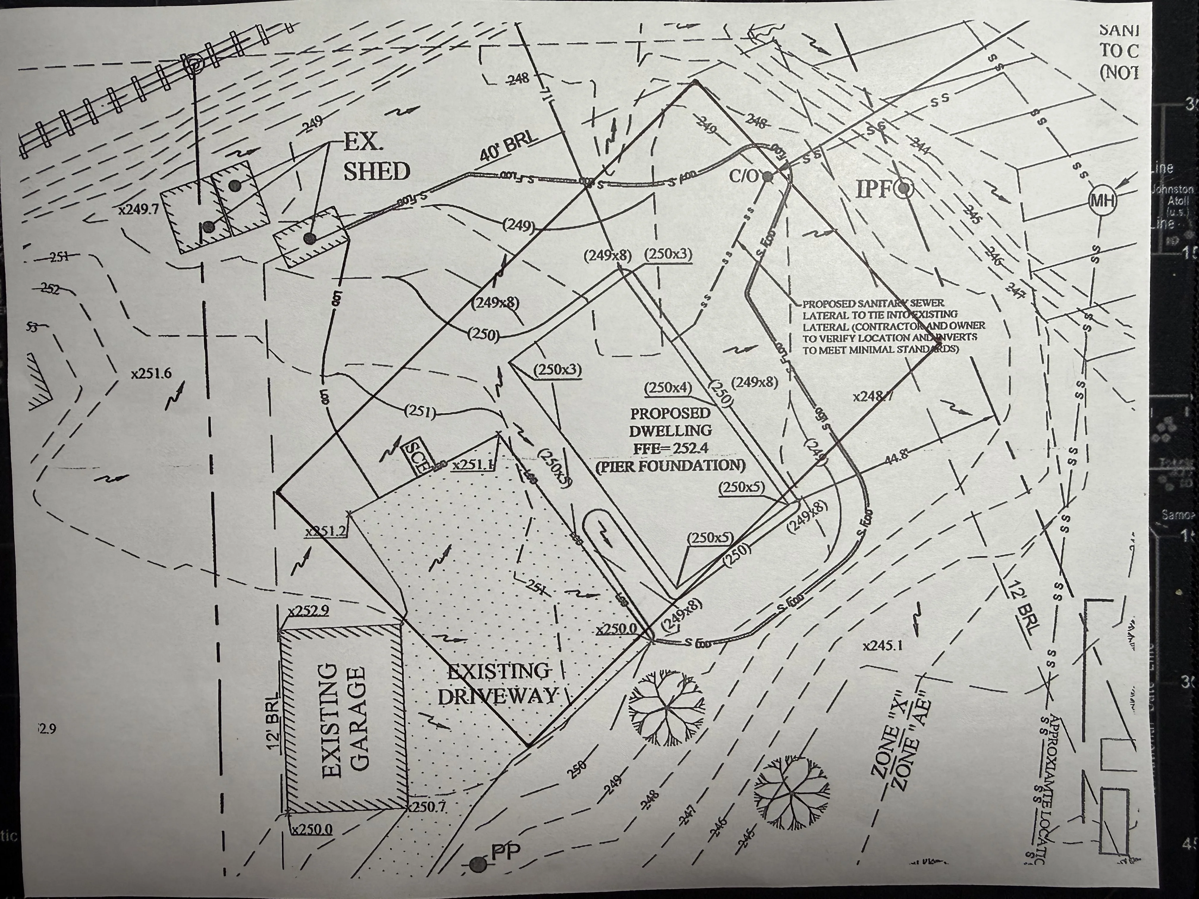
This page shows the translation chain: Peter sketches and intake drawings on one side, generated plan diagrams on the other. The point is to understand the building fast without pretending the drawings override the LDDs.
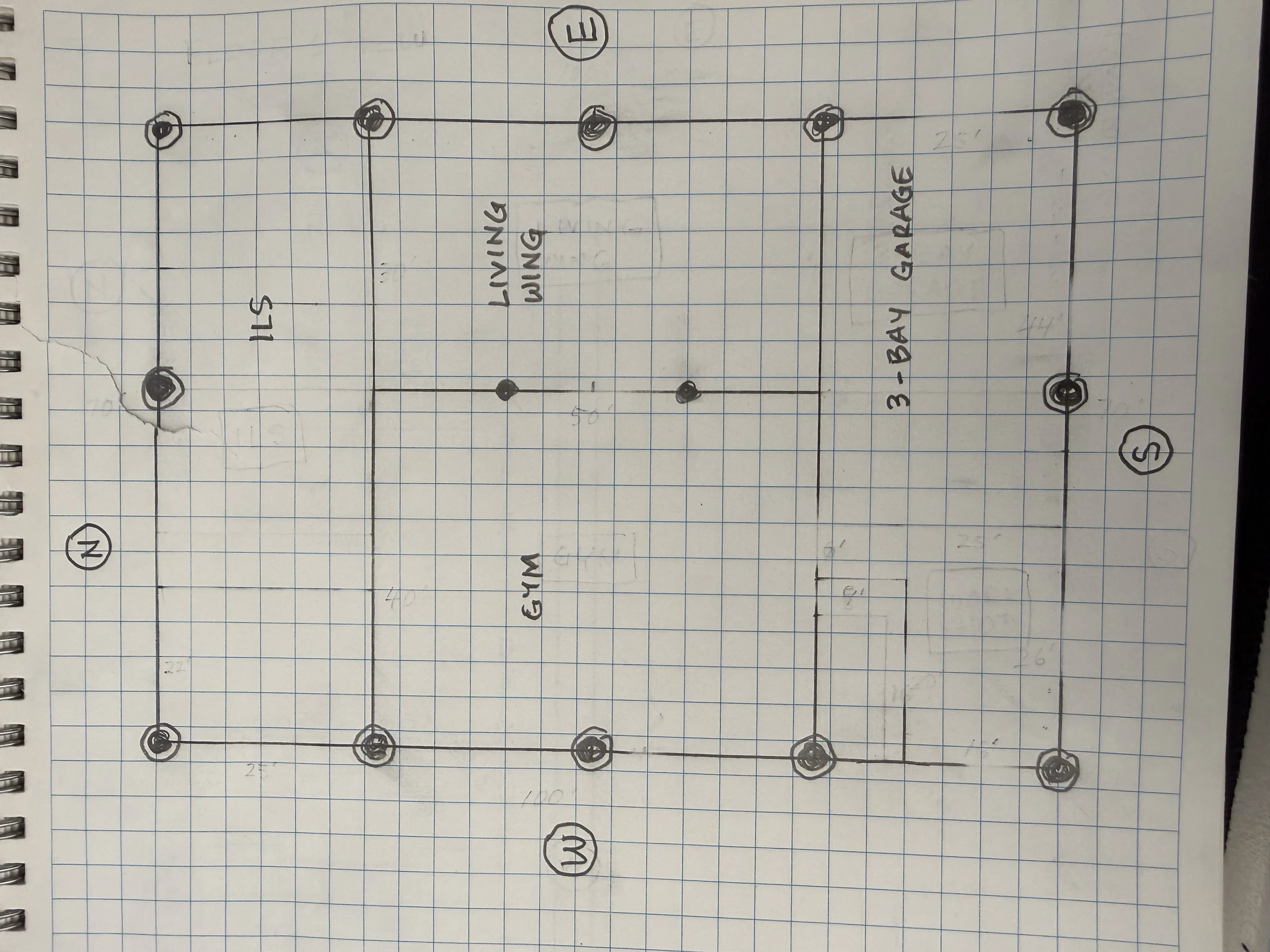
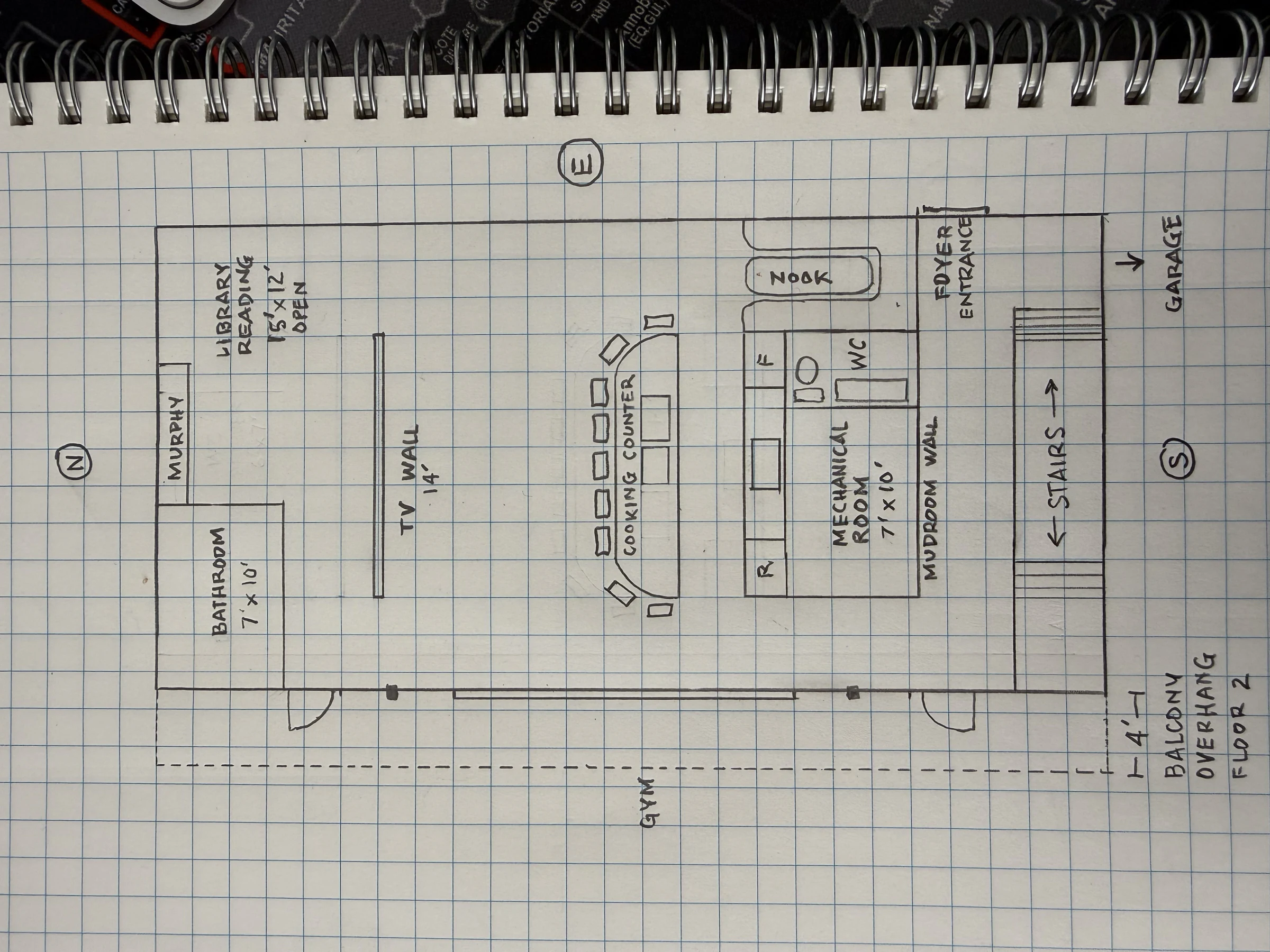
Level 1
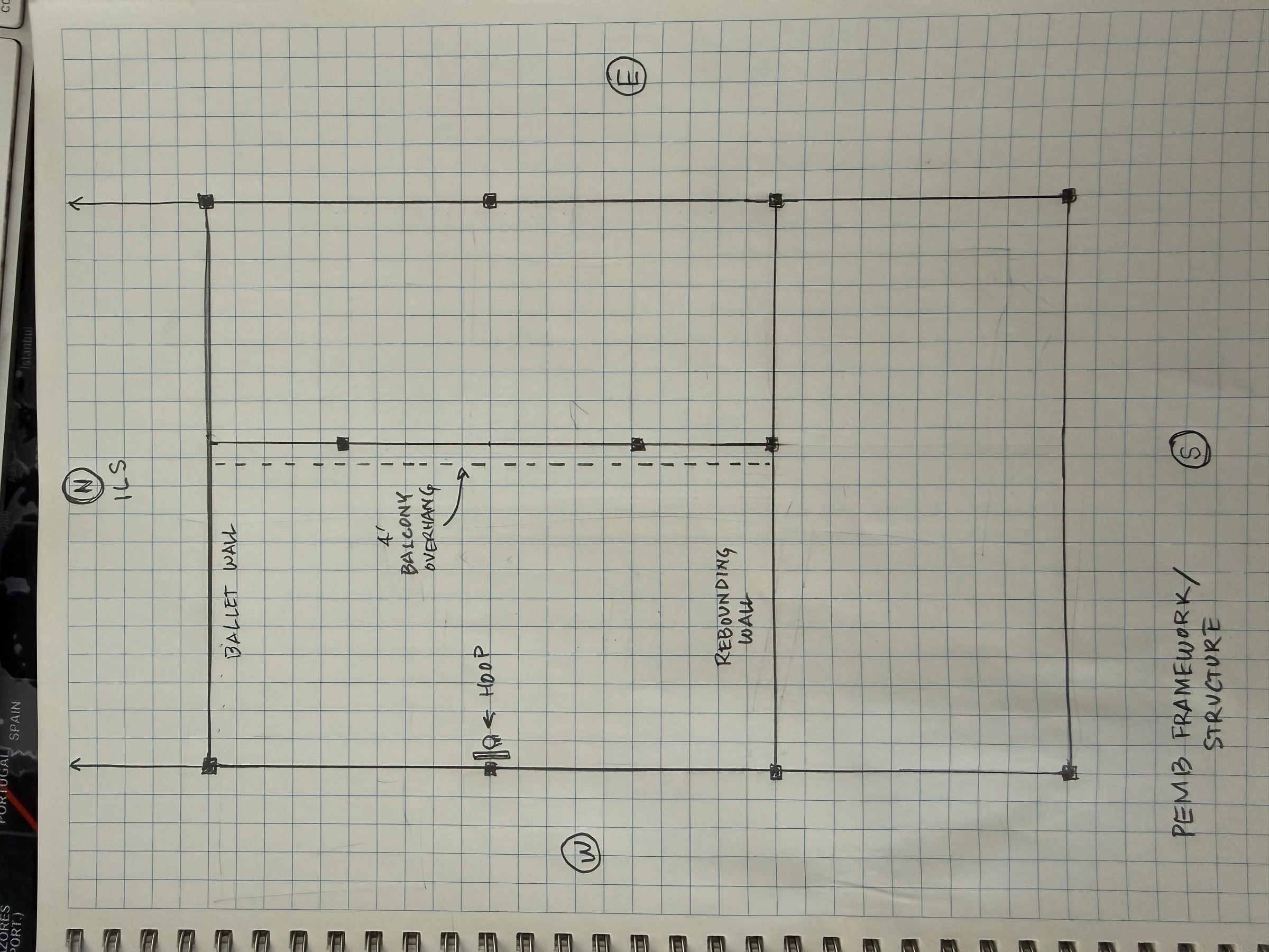
PEMB grid, central gym/living core, south workshop/garage bay, and major circulation.
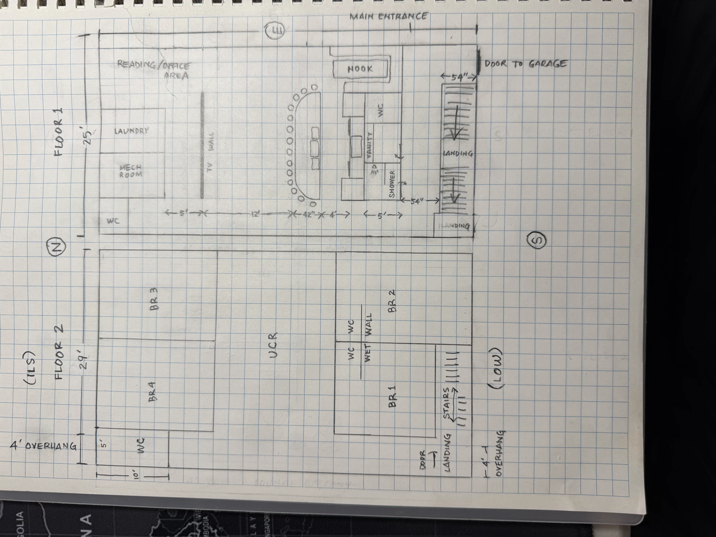
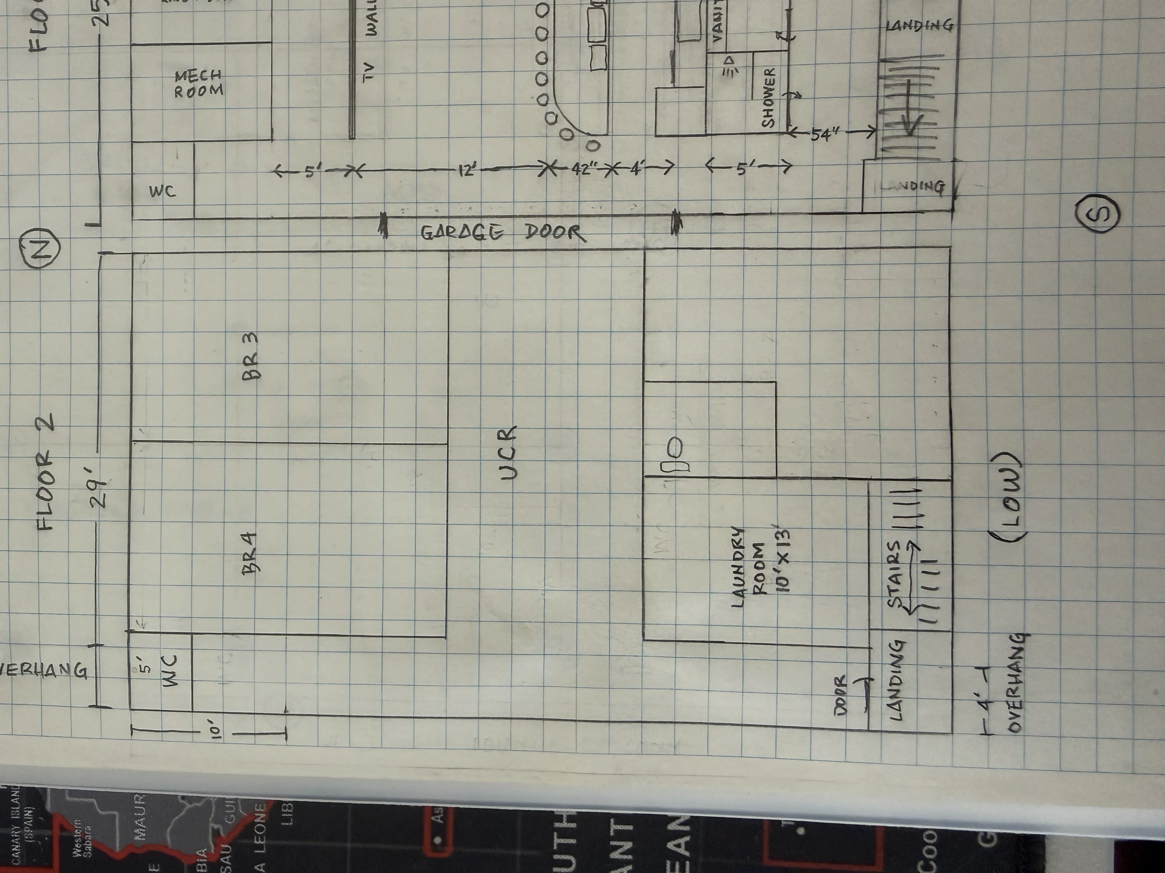
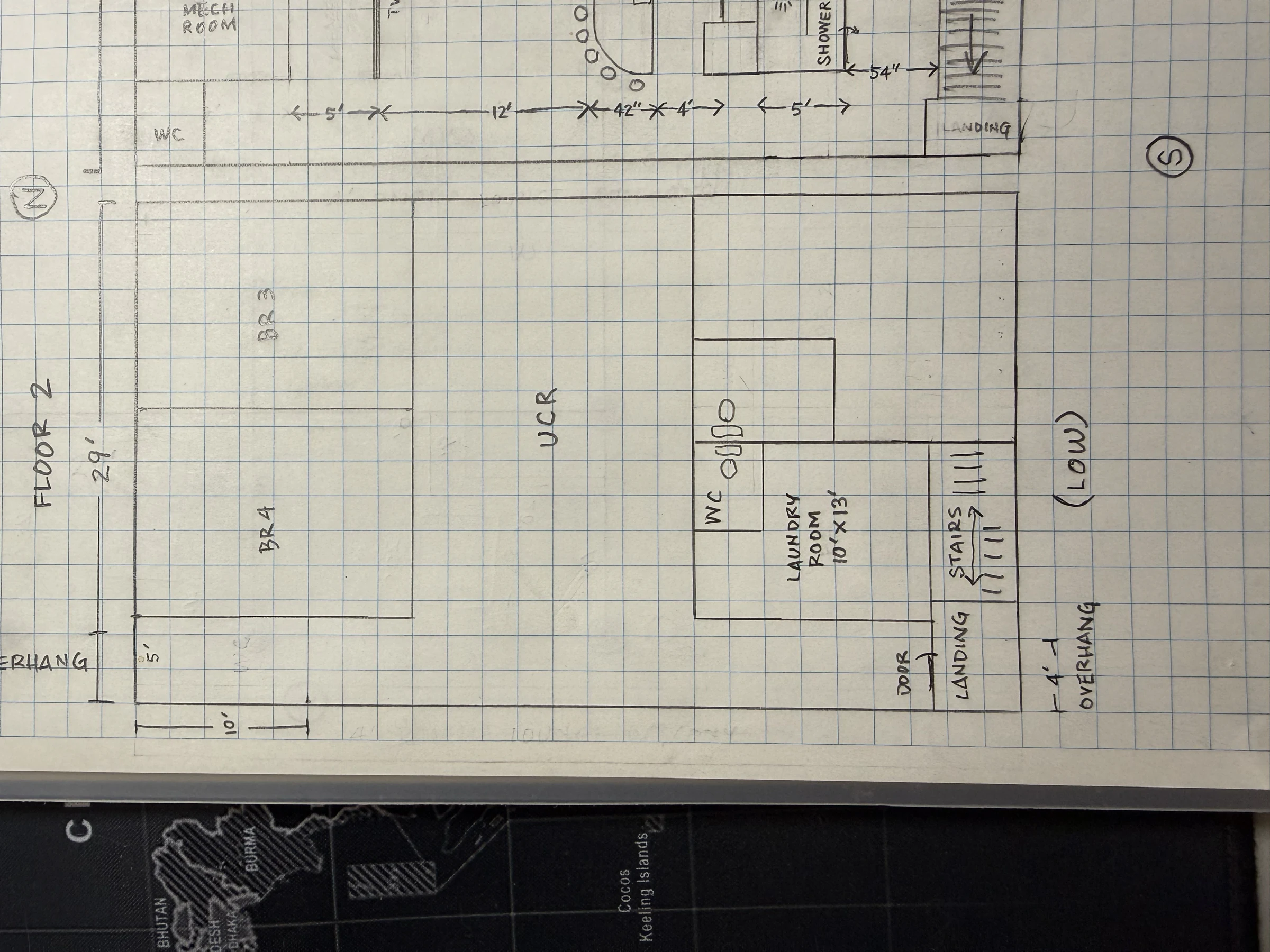
Level 2
Upper bedrooms, UCR, laundry, WC, and living-wing support logic that still needs a formal Floor 2 LDD.
Systems plans
HVAC, radiant, electrical, plumbing, lighting, ceiling, and MUA diagrams generated from the CAD scripts.
CAD downloads
PDF, SVG, PNG, and DXF exports live in the CAD register for deeper review.
Sketch to Plan Pairs


Sketch Library
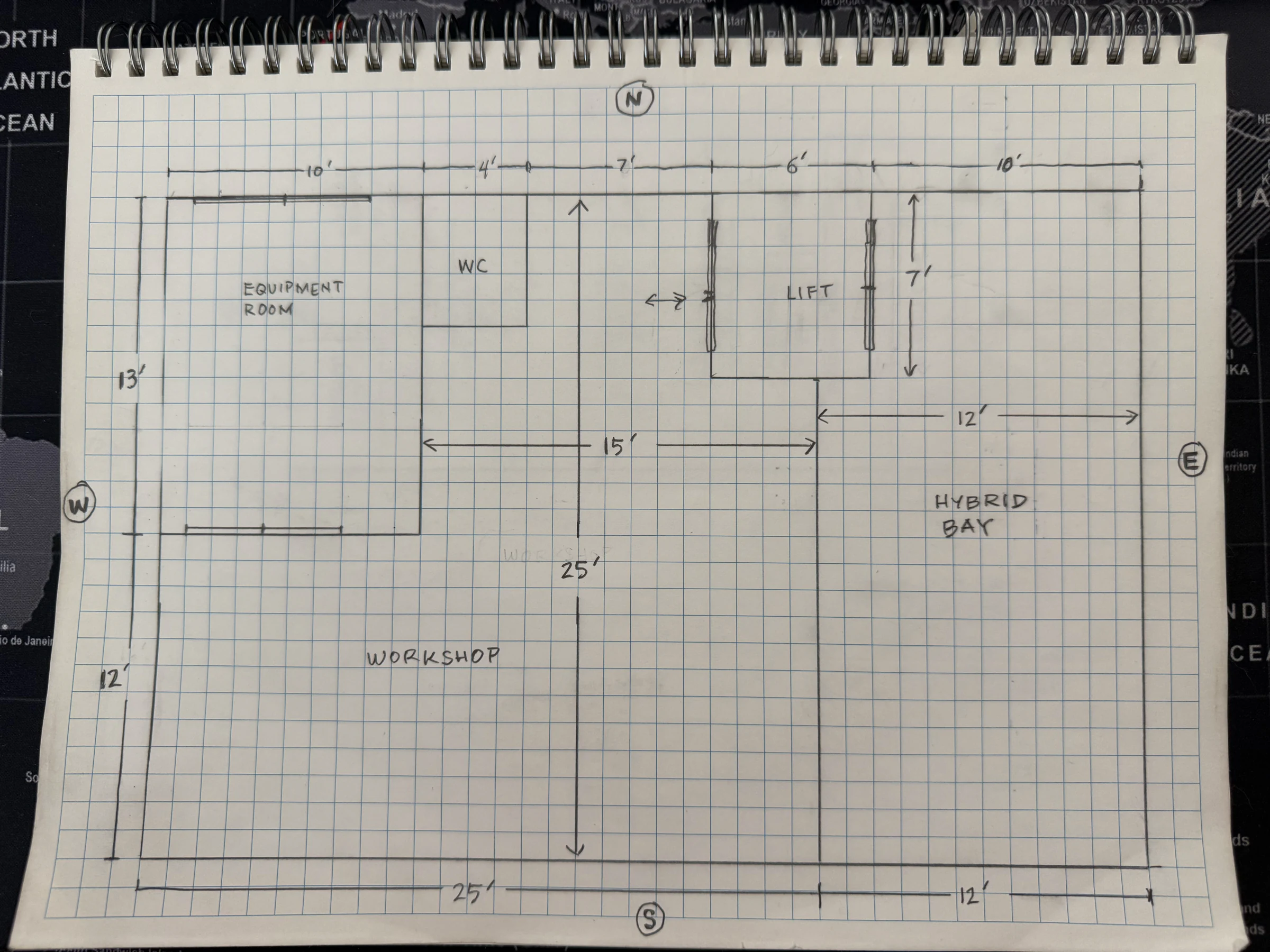
Hand sketches + footprint estimates from the 634 Grant Ave intake. Click any image to enlarge. Each will eventually find a home embedded in the relevant LDD (PEMB sketches → LDD-01, living wing → LDD-06, workshop → LDD-14, etc.).
Working references

Drawing Intake Rules
- Keep editable CAD source files in `cad/source/`.
- Publish reviewable web exports in `cad/exports/` or `diagrams/`.
- Link every floor-plan region back to controlling LDDs.
- Do not let drawings silently override LDD intent; promote conflicts through Project Command first.