LOCKED v2.0 needs mech designer · Two-tier comfort + maintenance strategy

LDD-02 · Radiant Slab System

📋 Unified by LDD-30 Central Mechanical Core Master Strategy (v6.0, 2026-05-17). LDD-30 §23–§24 codify the radiant slab assembly principles, gypcrete topping, and pressure-testing protocol that must be verified before and during slab placement. Garage/workshop loops (south manifold, Zone 3) are independently controlled and thermally separated from residential comfort loops (north manifold, Zone 1).

One-line intent

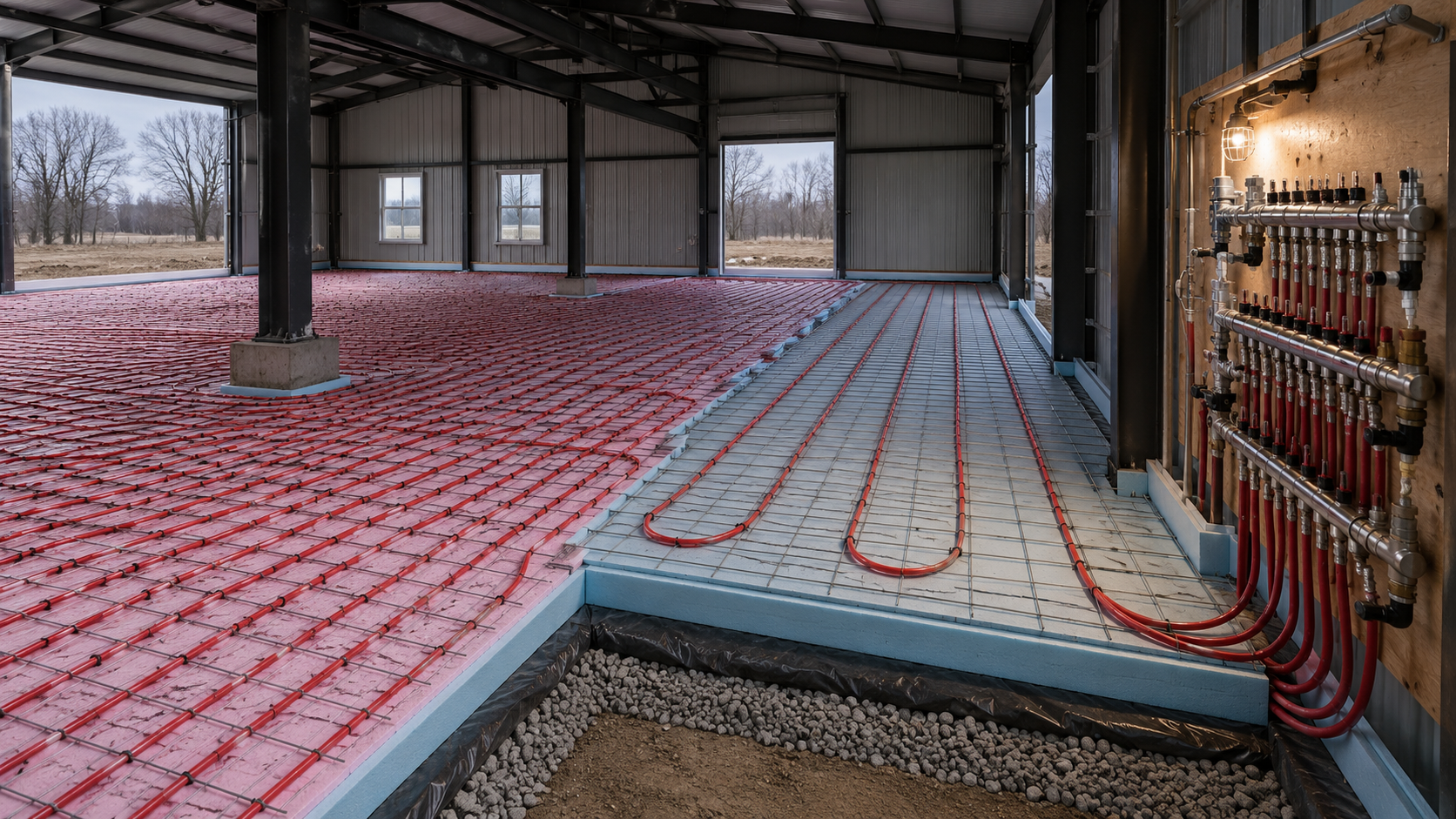
Comfort-density tubing for people; maintenance-density tubing for garages — warm where life happens, tempered where function matters.

Design intent · AI render

FPO · AI render AI-rendered pre-pour view of the hydronic radiant slab — partial cutaway showing comfort-density tubing at 6-9 inch on center on the left meeting maintenance-density tubing at 12-18 inch on center on the right, polished stainless central manifold mounted on the spine wall, rigid insulation and wire mesh assembly visible, dark charcoal PEMB frame overhead in cool overcast afternoon light
Radiant slab intent render — pre-pour view at the boundary between comfort-density and maintenance-density tubing tiers, central manifold visible. For Position Only: AI-generated from the prompt below. Click to enlarge.
Codex prompt & how to regenerate

To regenerate: hand the prompt below to Codex / ChatGPT with image generation enabled (or any gpt-image-1 / DALL-E 3 endpoint), save the result as site/diagrams/02-radiant-fpo.png, redeploy. Page picks it up automatically.

Recommended params: model gpt-image-1, aspect 16:9, size 1536 × 1024.

Prompt:

Architectural mid-construction rendering of a hydronic radiant slab system during the pre-pour phase, inside a pre-engineered metal building (PEMB) residential barndominium. Wide-angle photoreal view looking diagonally across the slab field, capturing the tubing layout at the boundary between two density tiers, in cool overcast late-afternoon light. 16:9 aspect. No people in frame.

Spatial hierarchy. The view shows a partial slab field roughly 40' across with the radiant tubing pattern visibly arranged on top of rigid-foam insulation panels. The PEMB structural frame is visible in the background — dark charcoal steel columns and purlins overhead, a generous open volume — but the focal subject is the slab assembly itself, captured mid-installation before concrete pour.

Two-tier tubing density (the hero element). A clear visible boundary line crosses the foreground where two tubing densities meet: on the left, comfort-density tubing at ~6"–9" on center, the loops tight and orderly — destined for a living-wing slab. On the right, maintenance-density tubing at ~12"–18" on center, the loops more widely spaced — destined for a garage bay. The PEX tubing is bright red or warm-orange, secured to a clean steel wire mesh with restrained zip-ties, organized in serpentine loops that read as carefully engineered, not improvised.

Manifold panel (compositional anchor). At the right edge of frame, mounted to a temporary plywood backer attached to the spine wall framing, a polished stainless-steel hydronic manifold cluster — multiple supply and return ports, ball valves, and labeled flow meters. This is the "central manifold" of the three locked clusters. Clean copper or stainless lines visible coming up from the slab and turning into the manifold. Restrained, mechanical, well-organized — the opposite of a chaotic residential utility closet.

Slab assembly (bottom to top, visible in a partial cutaway corner). Show the assembly stack clearly in one foreground corner: compacted subgrade, stone base, vapor barrier, continuous rigid insulation panels (rigid foam blue/pink), wire mesh reinforcement, and the PEX tubing laid on top. The slab-edge insulation strip at the PEMB perimeter column is clearly visible — continuous thermal break detail.

Surroundings. Background PEMB frame in dark charcoal, partially clad with medium warm-gray IMP envelope panels. The spine beam runs N-S overhead, supported by an offset interior column to one side of frame — the column carries down to a deep pier footing visible at slab level. No people, no construction debris, no scattered tools — the frame is calm, the work is in progress, the slab is ready for concrete.

Lighting mood. Soft, cool, overcast late-afternoon. Even diffuse light from the still-open envelope openings. No dramatic sun rays. The mood is meticulous, careful, ready — a hydronic system about to be entombed for 50 years. Subtle warm work-light glow from a single temporary task light at the manifold panel.

Material palette. Dark charcoal PEMB steel, light-warm concrete substrate (under the insulation), rigid foam insulation in pale blue or pink, polished stainless manifold, warm-red PEX tubing, restrained galvanized wire mesh, medium warm-gray IMP envelope panels in background. No bright colors beyond the functional red of the tubing.

What this is NOT (critical). Do NOT render as: a commercial flooring catalog illustration, an HVAC textbook diagram, a cartoonish exploded axonometric, a residential subdivision job-site photo with mud and footprints, or an industrial radiant-system marketing brochure. NO blue or green PEX (the project uses red-orange industry standard for radiant supply). NO chaotic tubing crossings. NO sheet-metal-roof imagery. NO bright orange or yellow safety equipment in frame. NO heavy concrete trucks or pumps visible. NO post-pour finished floor — the render captures the moment BEFORE the pour.

Style direction. Professional architectural visualization, photoreal, evenly exposed. Calm, technical, restrained — the mood of careful engineering work in progress. Neutral camera at slight elevation (~4'-5' eye-level, slightly looking down at the slab work), wide angle equivalent to ~28mm full-frame, framing the tubing density boundary as the geometric anchor and the manifold panel as the compositional resolution. Sharp focus throughout, no shallow DOF. Should feel like an architectural-process documentary photograph, not a contractor's iPhone snap.

Tubing density tiers

TierSpacing (planning)WhereGoal
Comfort6–9" OC (tighter at perimeter glazing)Living wing · ILS living/bed/bath · downstairs baths · primary circulationBarefoot comfort, stable winter occupancy
Athletic / mid9–12" OCGym slabReal comfort during use
Maintenance12–18" OCSouth garage bays · ILS garage · hybrid receiving · lift/serviceSlab tempering, dry storage, usable winter garage

Three manifold clusters

Upper floor strategy

Slab assembly (bottom → top)

  1. Compacted subgrade · stone base
  2. Underslab vapor barrier · rigid slab insulation (continuous)
  3. Reinforced concrete slab · hydronic tubing
  4. Finished slab surface

✅ Foundation cascade — withdrawn 2026-05-15 PM

Earlier draft warned of a "pier foundation cascade" risk. Per builder rebuttal, this was a misreading of architectural terminology. In a PEMB-residential context, "piers" = deep concrete pile footings under the steel column grid + grade beams. The slab itself remains a continuous monolithic slab-on-grade with integrated radiant tubing over continuous rigid insulation. No "wood subfloor on piers" assembly is contemplated. The radiant strategy in this LDD applies as written.

Execution rules

Open items / engineer review

Cost drivers

Tubing + labor $35–45K (~6,000 sqft slab, weighted avg). Manifolds $12–21K. Slab insulation $9–15K. Gypcrete upstairs $15–25K — biggest single cost lever. Total $90–125K.

Air-gap concerns

  • Two §11 sections in source LDD. Document was edited in pieces; needs cleanup pass.
  • Bathroom comfort spacing not specified — typically 4–6" near showers, not 6–9" generic.
  • Workshop classification wishy-washy. Pick comfort or mid; don't leave open.
  • Gym slab strategy unresolved — locked at athletic comfort, options list contradicts.
  • Bedroom radiant not addressed — only ducted is mentioned. Cold floor in winter is a regret.
  • 85°F surface cap from LDD-24 flooring is a real constraint on operating curve.

Cross-references

→ Outputs to

LDD-12 ceilings · LDD-05 HVAC · LDD-15 mech room

← Inputs from

LDD-01 slab · LDD-11 slab edge · LDD-24 85°F cap

Diagram

Radiant slab plan — building footprint with two-tier zone keying (comfort vs maintenance density), three manifold clusters keyed at north / central mech room / south, and tubing serpentine pattern hint
Radiant slab plan — two-tier zoning (comfort vs maintenance density) across the footprint with three manifold clusters at north (ILS), central mech, and south. Layer-2 CAD from cad/source/02-radiant.py. Click to enlarge.