LDD-28 · Kitchen Makeup Air (MUA) Infrastructure Routing
Status: 🟢 LOCKED v1.0 — adopted 2026-05-16. Supersedes the boost-ERV makeup-air approach previously locked in LDD-05 and LDD-07.
Naming note: Peter labeled this draft "M-02" (mechanical-system family). Filed here as LDD-28 to keep one canonical numbering sequence; the M-02 label is preserved as an alias.
Decision history: A prior decision (2026-05-15 PM) had retired this MUA line in favor of a boost-capable ERV that served dual duty as kitchen makeup air. Reversed 2026-05-16 — Peter chose the dedicated MUA for: (a) the architectural value of the east-facade flush charcoal louver + under-stair displacement register, (b) better tempering control + pressure balance during Hurricane Mode, (c) a smaller standard residential ERV freed for IAQ-only duty (cleaner spec, better daily performance). Net budget impact: ~$6–14K over the prior boost-ERV approach. LDD-05 + LDD-07 have been updated to drop the boost-ERV spec.
Cross-references (Peter's labels mapped to this set)
Peter's draft used cross-ref labels that don't match the actual LDD numbering. Mapped here:
| Peter's label | Actual LDD in this set |
|---|---|
| LDD-02 Foundation & Slab | LDD-01 Structural PEMB (foundation) + LDD-02 Radiant Slab (slab) |
| LDD-14 Kitchen Ventilation | LDD-07 Cooking + Island Ventilation |
| LDD-07 Cooking Counter Layout | LDD-07 Cooking + Island Ventilation (correct) + LDD-20 Primary Social Counter (counter layout) |
| "First Floor Living Wing Elevation Study" | Closest match: LDD-06 Living Wing HVAC |
One-line intent
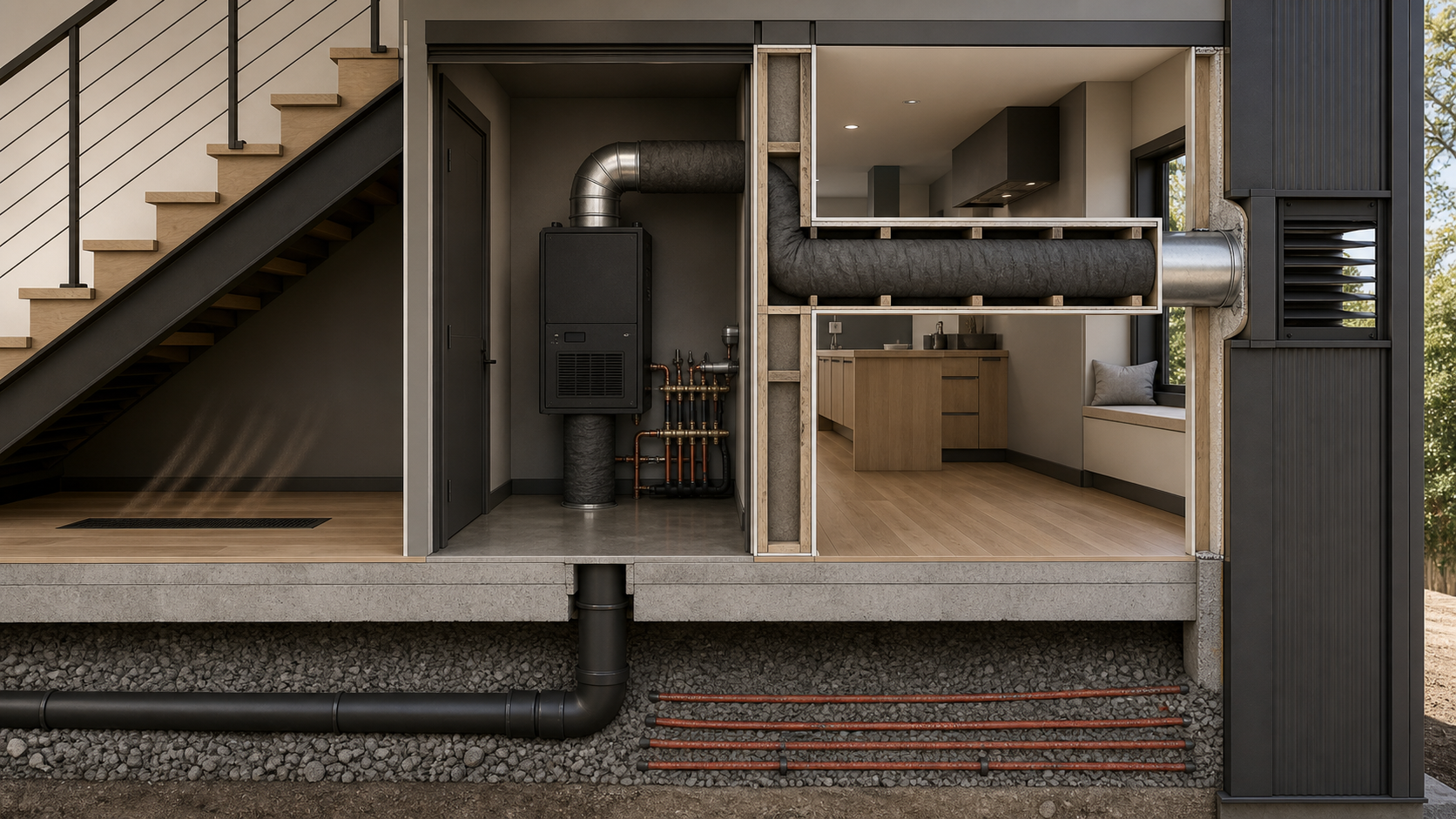
Dedicated tempered makeup air unit interlocked with the kitchen exhaust — intake at the east facade hidden in a charcoal flush louver, routed through an acoustically-lined partition wall to a wall-mounted unit in the mechanical room, then under-slab south to an invisible under-stair floor register that diffuses tempered air into the space with zero visible utility.
Design intent · AI render
Why this matters
The kitchen exhaust (LDD-07) runs well above 400 CFM in "Hurricane Mode," which triggers IMC makeup air requirements and threatens to depressurize the tightly-sealed IMP envelope (LDD-11) — backdrafting flues, sucking weatherstripping, slamming doors, killing combustion appliances. The mechanical answer is some form of matched makeup air; the architectural answer is to make that mechanical answer invisible. Peter's routing — east facade louver hidden in trim, partition-wall chase, under-stair diffuser — does the second part beautifully. The first part is what the LDD-05/07 conflict above is really about: is the ERV-as-MUA solution code-compliant and operationally sufficient, or do we need this dedicated unit?
Locked decisions (per Peter, v3.0)
System mandate
- Dedicated variable-speed tempered MUA unit, electronically interlocked low-voltage to the kitchen exhaust blower
- Ramps proportionally with exhaust CFM
- Maintains neutral pressure balance in the IMP envelope
East-facade intake
- 12"–14" round galvanized duct
- Horizontal penetration through east IMP wall
- Centerline at 11'0" AFF (above human sightline, above splash zone)
- Shifted as far north along the east wall as PEMB framing permits — protects the foyer entrance visual clarity
- Architectural flush louver, heavy-gauge, factory powder-coated to match the dark charcoal trim/window frame tone
- Integrates with the high horizontal trim geometry of the facade
Horizontal wall chase
- Routes westward inside the partition wall between cooking counter zone and breakfast nook / powder room
- Partition framed as minimum 2×6 or double-stud utility wall to house the duct
- Duct tightly wrapped in high-density insulation or specialized acoustic lagging before drywall enclosure — no "wind rush" audible in the nook during Hurricane Mode
Vertical drop into mechanical room
- Smooth long-radius 90° elbow at the wall threshold of the 7'×10' central mechanical room (LDD-15)
- Vertical drop down the inside face of the mech room wall, into the top intake collar of the MUA unit
MUA equipment
- Wall-mounted on the south wall of the mechanical room (mudroom wall axis)
- Cabinet contains: intake fan blower, motorized dampers, high-efficiency filtration
- Mounting strategy isolates fan harmonics + mechanical vibration inside the dedicated service room behind an insulated service door
Hydronic tempering
- Integrated hydronic heating coil piped into the primary radiant boiler loop (LDD-02)
- Pre-heats incoming sub-freezing winter air to a stable 60°F–65°F
- Prevents thermal shock + draft discomfort in the living zones
Under-slab discharge routing
- Tempered supply exits the bottom of the MUA, dives vertically through the slab inside the mech room envelope
- Below slab: heavy-wall PVC or coated spiral pipe routed south, beneath mudroom wall + foyer footprint
- Sits in the crushed-stone base below the structural slab
- Must be kept completely separate from any radiant PEX loops (LDD-02 coordination is critical)
Under-stair discharge
- Under-slab line surfaces beneath the southern structural stair (LDD-19)
- Terminates at a flush-mounted linear floor register tucked inside the open dead space beneath the stairs
- Stair underside acts as a natural baffle — breaks velocity, muffles air movement noise
- Air pools invisibly in the low-traffic southern zone, gently overflows into living + cooking spaces
- 100% draft-free, zero visible floor utilities
Routing diagram (Peter's ASCII)
[Exterior East Louver at 11' AFF] ──> (Horizontal Wall Chase behind Nook/WC)
                                                      │
                                                      ▼ (Vertical Drop inside Mech Room)
                                         [MUA Unit on South Mech Wall]
                                                      │
                                                      ▼ (Slab Dive)
   [Floor Register Under Stairs] <── [Under-Slab PVC Duct Run Heading South]
Open items / requires engineer review
- Resolve the LDD-05 / LDD-07 / LDD-28 conflict (banner above) — this is the v1.0 blocker.
- IMC requirement verification. Peter states "dedicated tempered MUA is legally required for 400+ CFM per IMC." IMC §505/§506 requires makeup air for exhaust over 400 CFM but allows it from any source that maintains pressure balance — including ERV/HRV in boost mode. The ERV-boost solution in LDD-07 was designed to meet the same IMC requirement via a different mechanical path. Confirm with the mechanical engineer whether IMC actually requires dedicated MUA, or whether either solution satisfies the code.
- Under-slab PVC + radiant tubing sequencing. Peter calls this out himself — the MUA sleeve must be in the crushed-stone base before PEX is laid and before the slab is poured. Coordinate with LDD-02 radiant slab installer + concrete sub. Once PEX is in, a forgotten sleeve means saw-cutting.
- PVC duct condensation risk under-slab. Cold winter intake air inside the PVC, warmer crushed-stone base outside — the PVC exterior is below dew point and may condense moisture in the granular base. Insulated PVC? Vapor barrier? Confirm.
- Mech room space planning. LDD-15 is 7'×10' = 70 sf. A wall-mounted MUA cabinet (typically ~3'×4' + service clearance ~3' in front) eats meaningful floor area. Verify the room still accommodates the radiant manifold + boiler + ERV + water heater + electrical equipment already implied.
- Hydronic coil load on radiant boiler. Tempering 1,000–1,500 CFM of -10°F outdoor air to 65°F = ~75°F lift × CFM × 1.08 ≈ 80–125 kBTU/h at peak. Add that to radiant slab load. Confirm boiler is sized for both, or specify a dedicated tempering source.
- East-facade louver penetration in IMP. IMP penetrations are thermal bridges + air-sealing risks. The "flush-mounted architectural louver" needs an air-tight installation gasket + thermal break. Coordinate with LDD-11 envelope penetration details.
- Acoustic lagging material spec. "High-density insulation or specialized acoustic utility lagging" — pick: mineral wool wrap, mass-loaded vinyl, neoprene foam, or proprietary duct silencer. Different choices have different fire-rating + acoustic performance.
- Pre-heat target validation. 60–65°F is "comfort neutral" but aggressive on the boiler at peak. A 50–55°F target saves significant winter heating energy and the living-zone occupants likely won't notice a 5–10°F difference at the diffuser since the air mixes with room air before reaching breathing height. Trade-study with the mechanical engineer.
- Under-stair "dead space" must actually exist. Coordinate with LDD-19 doors + stairs — if the southern stair is closed-string with storage or a coat closet underneath, there's no diffuser cavity. Lock this into the stair design now.
- Floor register coordination with LDD-24 flooring. Flush-mounted linear register transition to the gym-adjacent or living-wing floor finish. Pick the register material + edge detail.
Cross-references
- ← LDD-01 PEMB structural — east-wall louver penetration through PEMB cladding + framing; partition-wall chase reinforced to 2×6/double-stud framing.
- ← LDD-02 radiant slab — under-slab PVC routing must NOT conflict with radiant PEX loops; sequencing critical.
- ← LDD-05 HVAC system — ERV downsized to standard residential ($3–5K) for IAQ-only duty now that MUA handles kitchen makeup air.
- ← LDD-07 cooking + island ventilation — kitchen exhaust interlocks with this MUA in Hurricane Mode (formerly proposed to interlock with ERV boost).
- → LDD-09 electrical — low-voltage interlock wiring between exhaust blower control and MUA fan ramp.
- → LDD-11 exterior envelope — IMP penetration detail at the east-facade louver; air-sealing + thermal break + charcoal color coordination.
- → LDD-15 mechanical room — equipment mounting + space planning + service clearance + acoustic isolation behind insulated service door.
- → LDD-18 interior materials — partition wall framing finish + the architectural louver charcoal tone matching trim/window frame palette.
- → LDD-19 doors + stairs — under-stair dead space must exist for the diffuser register; coordinate stair design.
- → LDD-24 flooring — flush linear floor register integration with floor finish.
Cost drivers
The MUA gross cost, with the offsetting savings from downsizing the ERV (no longer needs boost-capable spec):
| Component | Cost |
|---|---|
| Variable-speed tempered MUA unit (1,000–1,500 CFM) | $5–10K |
| Hydronic tempering coil (integrated) | $1–3K |
| Architectural flush louver, custom charcoal powder-coat | $1–3K |
| 12–14" galvanized duct + long-radius elbows | $1–2K |
| Partition wall framing premium (2×6 or double-stud) | $1–2K |
| Acoustic lagging for horizontal chase | $0.5–1K |
| Under-slab PVC routing + sleeve sequencing | $1–2K |
| Linear floor register under stair | $0.3–0.7K |
| Low-voltage interlock wiring + controls | $0.5–1K |
| Total | $11–24K |
The LDD-05/07 boost-ERV approach already costs ~$5–10K extra for the higher-spec ERV. So the net incremental cost of adopting LDD-28 over the boost-ERV solution is:
LDD-28 (~$11–24K) − boost-ERV premium (~$5–10K already in budget) = ~$6–14K net add
This is consistent with LDD-07's "saves $8–12K by eliminating MUA" claim — the conflict is real, and the dollars are real.
Air-gap concerns
- The LDD-05/07/28 conflict is the air-gap concern that matters most. Resolve before any of these systems go to bid. Surface this to the mechanical engineer at the next meeting.
- IMC code interpretation. Confirm that the boost-ERV approach actually satisfies IMC §505/§506. If it does, the cost case for LDD-28 weakens; if it doesn't, the cost case for LDD-28 becomes a code requirement.
- Under-slab PVC sleeve sequencing is unforgiving. This MUST go in before the slab pour. Add to the docs/todo.md pre-pour checklist alongside the radiant tubing photo/map/pressure-test item.
- The under-stair diffuser is the cleverest part of this LDD, but it depends entirely on the stair design. Stair under-space must remain open. Lock this into LDD-19 before any stair fabrication.
- Hydronic coil load on the radiant boiler is significant. 80–125 kBTU/h at peak is not trivial — verify boiler sizing accounts for radiant + MUA tempering simultaneous load. Better to learn this from the energy model than from a cold January morning.
- East-facade louver air-sealing in IMP. IMP joints are the project's biggest air-seal story. A 12–14" penetration with a louver = a known thermal bridge + an air-leak risk. Detail with the IMP manufacturer.
- PVC duct condensation under-slab. Verify the PVC spec handles cold-air condensation against warm crushed stone, or insulate the under-slab PVC.
- Pre-heat target 60–65°F is energy-intensive. Trade-study against 50–55°F target — likely saves significant winter operating cost without occupant complaint.
- Acoustic lagging fire rating. Mass-loaded vinyl is not Class A; mineral wool wrap is. Pick the material with the kitchen's fire-class environment in mind.
- Filtration spec not stated. "High-efficiency filtration media" — what MERV? Kitchen MUA into a tight envelope deserves MERV 11–13 minimum; MERV 16+ if HEPA is desired. Lock this into the MUA cabinet selection.
- Service access for filter changes. The wall-mounted MUA on the south mech room wall must allow filter access without removing other equipment. Confirm in the space-planning pass.
Diagram

Status
🟢 Green — LOCKED v1.0 (adopted 2026-05-16). Highest-priority follow-ups before bidding: (1) verify IMC §505/§506 interpretation with mechanical engineer — either solution satisfies the code in our reading, but get it confirmed in writing; (2) coordinate under-slab PVC sleeve sequencing with LDD-02 radiant slab pre-pour checklist (added to todo.md); (3) confirm LDD-15 mechanical room space planning accommodates the wall-mounted MUA cabinet alongside existing radiant + boiler + ERV + electrical equipment.